AI IoT Solar Street Lights with GPS Tracking for Remote Projects
October 31, 2026
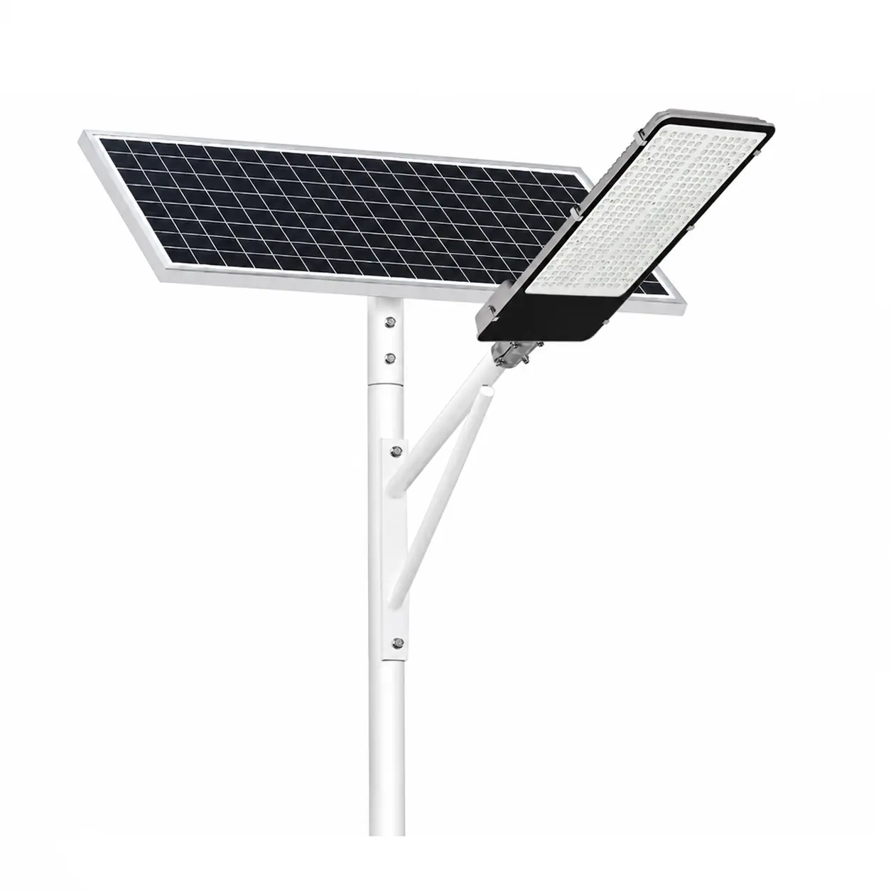
We find an AI IoT solar street-light system easier to evaluate when we separate its functions into layers. In our product materials, we describe a sensor that can sense traffic flow and weather conditions, an AI IoT MPPT controller with PC/APP, light, and remote-control functions, and Web or mobile APP management for status and commands. We also describe scalable integration with security cameras, early-warning broadcast systems, and meteorological monitoring equipment. These statements define useful architecture boundaries, but they do not prove a specific communication protocol, cloud supplier, API, camera model, or permission design.
In this article, we explain how these components fit together. For the concept and project-fit decision, see What Are AI IoT Solar Street Lights? Technologies, Functions, and Advantages Explained. For an actual tender or deployment, we recommend confirming every function against the selected model and project design.
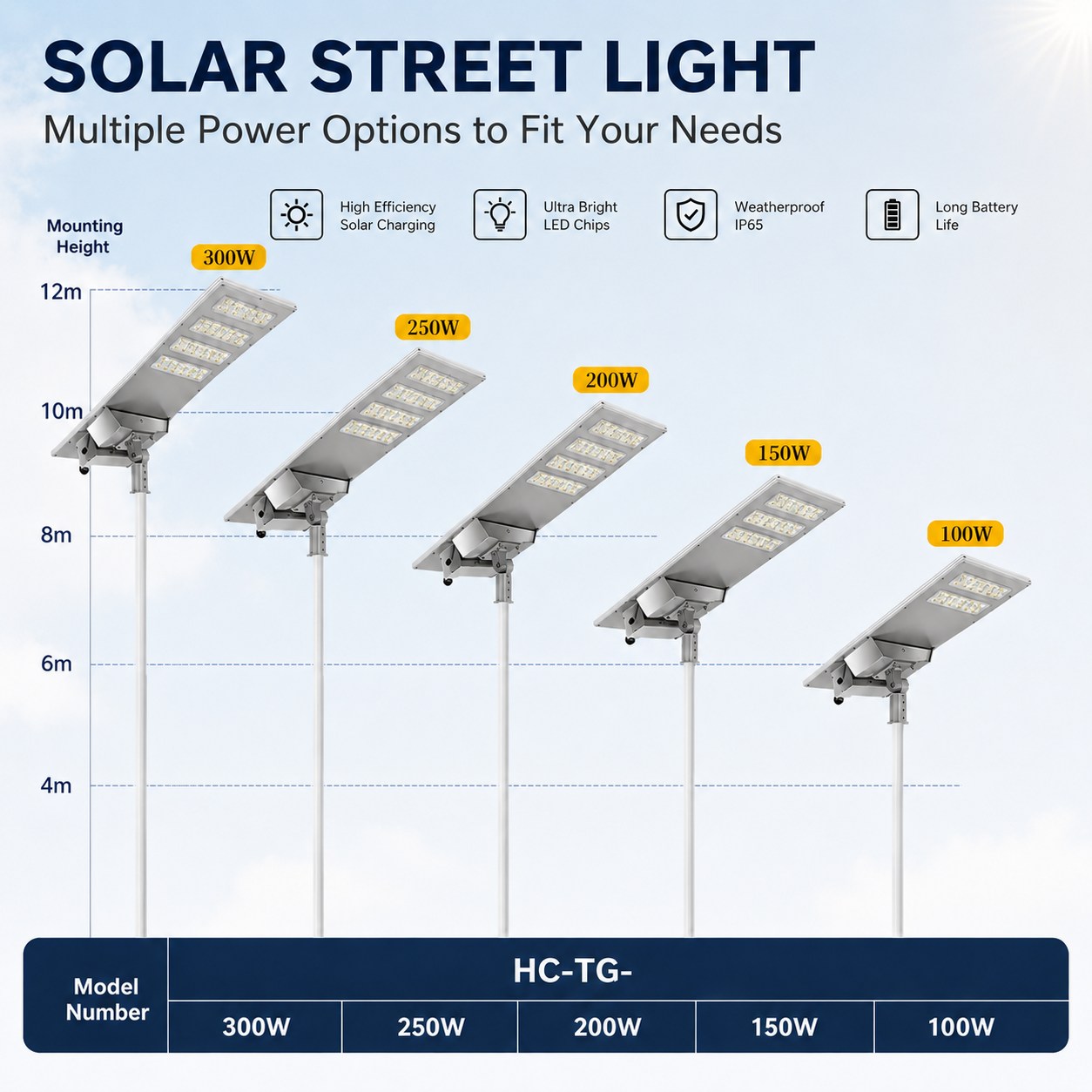
In our HC-CZSL-39 product description, we state that the sensor senses traffic flow and weather conditions and can support automatic adjustment of brightness and color temperature. At architecture level, we treat the sensor as the input layer. It observes a condition that may influence a lighting decision. Our record does not identify a universal sensor model, measurement accuracy, installation position, sampling interval, or algorithm. We therefore keep those details as project questions.
Our product record lists an AI IoT MPPT controller with PC/APP, light-control, and remote-control functions. MPPT relates to the solar charging and energy-management side; light and remote control relate to operation. We place the controller close to the lighting point in the high-level architecture, where it connects energy and lighting hardware to the management workflow. We do not infer a protocol, chip, wireless standard, or control-loop design from the words “AI IoT.”
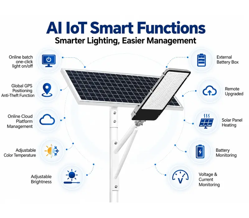
In our FAQ, we state that a Web or APP platform can adjust brightness, color temperature, on/off status, and wipers, and that Web browser and mobile APP platforms support data visualization. In a project workflow, our platform layer is where an authorized operator may review status, send a command, and respond to an alert. The exact screens, user roles, data-retention rules, and network dependencies still require confirmation.
Our comparison material describes scalable integration with security surveillance cameras, early-warning broadcast systems, meteorological monitoring equipment, and other requirements. We use that as a design direction. It is not the same as saying a camera is built into every solar street light or that every model includes a ready-made camera interface. We treat external devices as a separate integration workstream with its own power, mounting, bandwidth, data, privacy, and acceptance requirements.
Our safest high-level model is:
sensing → local control → status visibility → remote command → field response
This model helps us and our buyers ask the right questions without inventing a technical stack. Which readings are collected? Which decisions happen locally? Which commands are allowed remotely? What happens if connectivity is interrupted? Is the command logged? Who can change it? Which external device receives the data? These questions are more useful than assuming that “cloud platform” means one standard architecture.
| Function | Lighting point / edge | Platform / management layer |
| Condition sensing | Sensor captures the supported local input | Platform displays the resulting status when configured |
| Charging and lighting execution | Controller manages the listed local control functions | Operator may send an approved remote command |
| Brightness or color adjustment | Fixture applies the command | User selects or schedules the change through the available interface |
| Fault response | Local hardware continues its defined safe behavior | Alert review, escalation, and maintenance planning |
| External-device integration | Pole-side power, mounting, and connection must be checked | Data routing, user access, and workflow must be checked |
We use this separation to prevent two common errors. First, a platform function should not be presented as proof that every pole has the same hardware. Second, a hardware feature should not be presented as proof that a project has remote access, network coverage, or permission to use it.
We recommend using a model-specific architecture checklist.
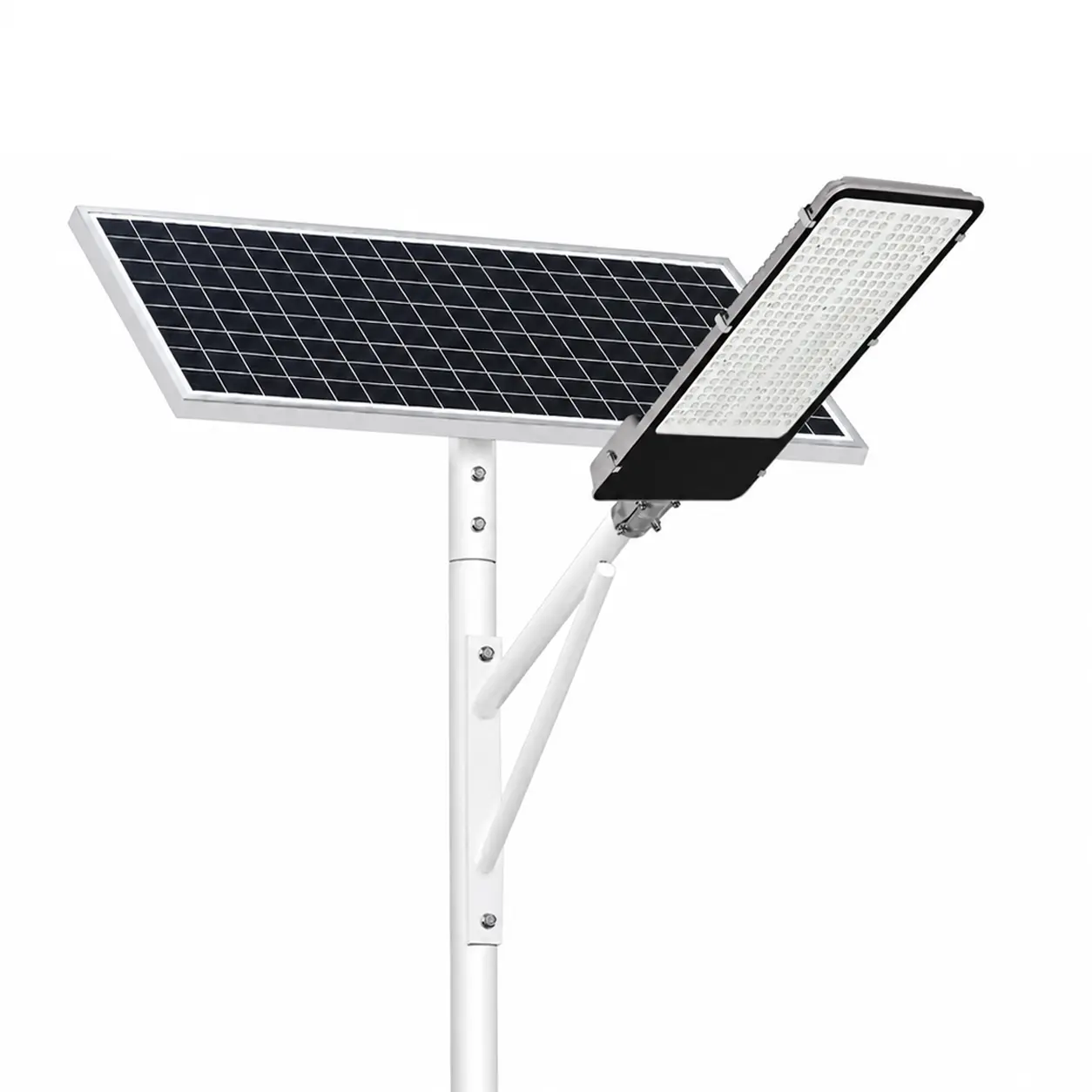
We confirm the model number, controller type, panel and battery arrangement, installation method, mounting height, lighting area, and environmental limits. Our HC-CZSL-39-100W record, for example, lists pole or wall mounting, a 4–6 m mounting height, a LiFePO4 external battery box, and a 3000K–6000K AI-adjustable color-temperature range. These values belong to that product record only.
We define whether the project needs traffic, weather, light-level, occupancy, or another input. We ask where the sensor is installed, what conditions it can detect, how the decision is made, and what happens when the reading is unavailable. We do not convert a general “sensor” statement into a performance specification without evidence.
We document local controls, remote controls, supported commands, connectivity method, coverage, offline behavior, firmware-update process, and command logging. We also confirm whether Web and mobile APP access are both included in the selected configuration, and which user roles can change settings.
For cameras, broadcasts, or meteorological devices, we confirm power budget, mounting, interface, bandwidth, data ownership, privacy requirements, storage, and acceptance tests. Our materials support treating these as scalable integration requirements; they do not remove the need for a project-specific interface review.
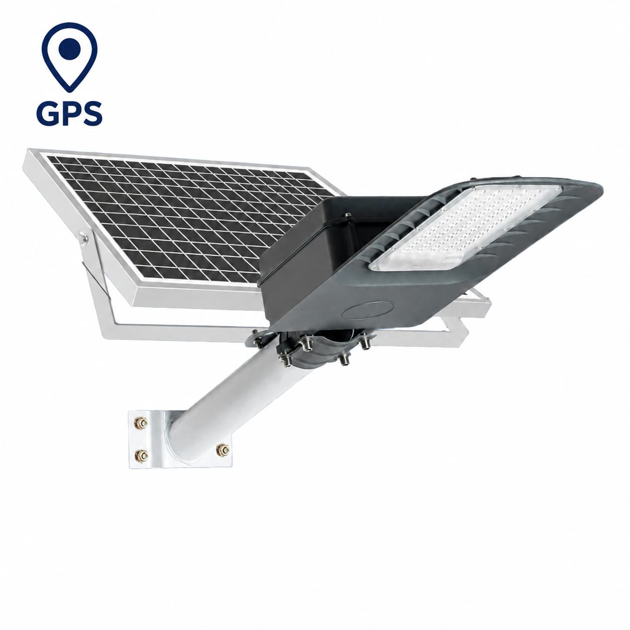
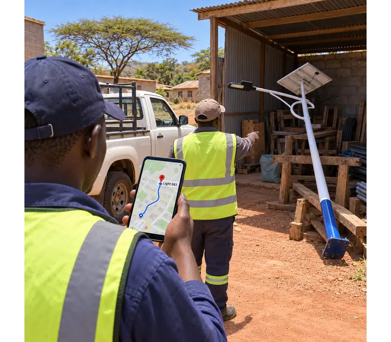
Our product description refers to real-time running-status checks, GPS positioning, remote firmware upgrades, 24/7 system supervision, and unique lamp identification. We confirm which of these are included through the AI IoT remote-monitoring and smart-management service, what service boundary applies, and how an alert becomes a field action. A dashboard without an owner, escalation rule, and closure record is not a complete maintenance process.

We use three evidence levels:
We write the first two levels as customer capability statements only when the exact scope remains visible. We write the third level as a requirement to verify. This distinction is especially important for solar street lights with pole mounting: the pole, fixture, controller, sensor, network, and external device may be supplied or configured by different workstreams.
Before approval, we prepare a one-page evidence pack containing the model number, component list, control diagram, network assumptions, external-device list, user roles, alert workflow, commissioning test, and acceptance evidence. We mark every line as confirmed, configured, or to be verified. That simple status label prevents a concept diagram from becoming an accidental product promise.

When you plan a connected solar-lighting project, share the site conditions, sensor and camera needs, monitoring workflow, connectivity method, mounting arrangement, and integration constraints with our team through the Werise global AI IoT system overview or the Werise contact page. We believe a sound architecture is not the one with the most boxes; it is the one where every box has a verified role, an accountable owner, and a clear handoff to the next stage.